Sunday, 25 May 2014

Star Network

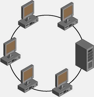
In a star network cable segments to a central connection unit or hub connect all computers.
Chief advantage of star topology over the bus topology over the bus topology is that, if a cable segment is broken, onlyonnected to the hub on that cable segment is affected.


Attachment Unit Interface (AUI)

Connector commonly are used with thick Ethernet cabling.  These device used a DB15 connecor to link o the network card.

Hardware utilized in a Bus Topology Network

Both thin Ethernet and thick Ethernet require the following additional network hardware to link the host.

  1. BNC Connector
  2. Terminator
  3. AUI Connector
British Novel Connector-  BNC connector enable the various thin-net Coaxial cable segments to interconnect each host has a T-connector that is used to link the cable segment to a host computer.


Wiring standard in a Bus Network

Computer network commonly are linked using network cabling.  The following are two wiring standards for communications on a bus network.

10Base2-  Also known  as thin Ethernet.  It allow network segment up o 185 meter on coaxial cable.

10Base5-  Also known as thick Ethernet, it allows network segments up o 500 meter in coaxial cable.


Local Area Network

There are basic type of local area network.
  1. Peer to Peer
  2. Server Based
Peer to Peer-  Peer to Peer network operate with no dedicated server on the network.  Each host functions as both a client and a server.  The user at each host determine what information or peripherals he is willing to share with the other members of the network.  Peer to Peer network generally are related to smaller organizations they do not scale will to larger ones.

Server Based Network-  At least one host is dedicated to server functionality.  Client computer do not share any information with other computer.  All data is stored on the central server .  Most corporate networks are based on this methodology.  Within a server based network, server can play several roles these roles include the following.

Directory Server-  These provide a central directory service for management of users groups and host object to allow for centralized authorization using the central directory.

Files and Print Server-  These provide a secure repository for all data.  They also can  manage point queues that provide access to network.  Searchable print resources.

Application Server-  These provide the server side of client/server application.  In a client/server environment, the client run a small version of the program that allow connectivity to the server.  The server side of the application is used to perform processor- intensive quires on behalf of the client.  Example of application server included Web server and database server.

Mail Server-  These provides electronics message capabilities for the clients of the network.
                                                                         or
A mail server is a program responsible for receiving routing and delivering e-mail message.

Security Server-  These provide security to the local network.  If it is connected to any larger networks such as the internet, security; server include firewalls and proxy servers.

Remote Access Server-  These enalble external data flow to occur between the network, or alternatively, use the technology known as tunneling or virtual private networks (VPNs) to connect to the remote network over a public network such as the internet.


Tuesday, 8 April 2014

Encoding and Modulatind

Data stored in a computer in the form of 0s and 1s.  To be carried from one place to another (inside or outside the computer), data are usually converted to digital signals.  This is called digital signal conversion or encoding digital data into a digital signal.
Digital to Digital Conversion-   Digital to Digital encoding or conversion is representation of digital information by the digital signal.  For Example, when you transmit data from your computer to your printer, both the original data and he transmitted data are  digital.  In this type of encoding, the binary ‘1s’ and ‘0s’ generated by a computer are translated in to a sequence are voltage pulses that can be propagated over a wire.
            Of the many mechanism for Digital to Digital encoding, we will discuss only those most useful for data communication.  These fall in to three broad categories Unipolar, Polar and By Polar.

Unipolar-  Digital transmission system work by sending voltage pulses along a medium link usually a wire or cable in most type of encoding one voltage level stands for binary ‘0’ and another level stands for binary ‘1’.  The polarity of a pulses refers to whether it is positive of negative.  Unipolar encoding is so named because it uses only one polarity.  This polarity is assigned to one of the two binary states, usually the 1.  The other state, usually the ‘0’ is represented by ‘0’ voltage.
DC Component-  The average amplitude of a Unipolar encoded signal is nonzero.  This creates what is called a direct current (DC) component (A component with zero frequency) when signal contains a DC component.  It cannot travel through media that cannot handle DC components.
Polar-   Polar encoding uses who voltage levels, one positive and one negative by using both levels, in most popular encoding methods the average voltage level on the line is reduced and the DC component problem of unipolar encoding is alleviated.
Polar encoding uses two levels (Positive and negative) of amplitude.
Non Return to Zero-  The NRZ encoding the level of the signal is always either of positive or negative.  The two most popular methods of NRZ transmission are discussed blow.
NRZ-L-  An NRZ-L encoding the level of the signal depend on than type of bit it represents.  A positive voltage usually mean s the bit is a “0”.  And a negative voltage means the bi is a 1 (or vice versa); thus the level of the signal is dependent upon the state of the bit.
In NRZ-L the level of the signal is dependent upon the state of the bit.

NRZ-I-  In NRZ-I an inversion of the voltage level represents a 1 bits,  It is the transition between a positive and negative voltage not the voltage themselves that represent a 1 bit is encountered.  The existence of 1s in the data stream allows the receivers to resynchronize its timer to actual arrival of the transmission.  A string of ‘0s’ can still cause problems.  But because ‘0s’ are not as likely, they are less of a problem.
In NRZ-I the signal is inverted if a 1 is encountered.
Bipolar-   The ‘1s’ are represented by alternating positive and negative voltages.  If  the first ‘1’ bit is represented by the negative amplitude, the third by the positive amplitude and so on.
In bipolar encoding we use three levels positive zero and negative.          
Bit Rate and Baud Rate-  Two terms use frequently to data communication are bit rate and baud rate. “Bits rate is number of bits transmitted during one second.
Baud rate is refer to the number of signal units per second Baud rate is less than or equal to the bit rate.
Example-  An analog signal carries four bits in each signal element.  If 1000 signal elements are sent per second find the baud rate and the bi rate.

  Baud Rate= Number of signal element x 1000 bits per seconds
  Bit Rate=      Baud Rate X Number of bits per signal element
                         1000          X 4 =4bps

Example-  The bit rate of a signal is 3000.  If each signal element carries 6 bits what is the baud rate.

Baud Rate=Bit Rate X Number of bits per signal element
                     3000      X  6 =500 Baud per secound       

Monday, 31 March 2014

Frame Relay

Frame Relay is a virtual – circuit technology that provide low level (Physical and data link layer) service in response to the following demands.
Higher Data Rate at lower Cost-  In the post many organizations used a Wan Technology such as leased line or x.25 to connect single computer.  That data rate was relatively low.  Today, most organization use high speed LAN and want to use WAN to connect this LANs.  One solution to use “T-Line”, but these line provide only point to point connections, no many too many.  Creating a Mash Network out of T-Lines is a very expensive.  For Example – To connect 6 LANS, we need 15 T-Lines.  On the other hand, we need only six-T-Lines to connect the same six LANs to a frame Relay Network.  Frame Relay provides the same type of service at lower cost.
               
            Although the Frame Relay originally was designed o provide a 1.544-Mbps data rate (equivalent to a T-1 Line) today most implementations can handle up to 44.376 Mbps(equivalent to a T-3 Line).
Virtual Circuits-  Frame Relay operates using virtual circuits as opposed to the actual circuits that leased Lines used.  These virtual circuits are what link together the thousand of devices connected o he providers “Cloud” There are two type of virtual circuits permanent and switched.
            Permanent virtual circuits (PVCs) are by far the most common type in use today.  What “permanent” means here is the Telco creates the mapping inside their gear and as long as you pay the bill, they will remain in place.

            Switched virtual circuits (SVCs) are more like a phone call.  The virtual circuit is established when data needs o be tansmitted, then  it’s taken down when the data transfer is complete.